
Engine Management Megasquirt DIYPNP "How-To" - Step-By-Step Instructions


!!!! I NEED TO POST !!!!
Joined: Nov 2013
Posts: 2
The write up is for the DIYPNP and that is a different product than the MSPNP, btw.
Those pictures were just stamped with the mustang site logo because that is where they were hosted. That site was also owned by the owner of this forum at one time. Everything listed is pertinent to the Miata as far as I can tell (I'm using a MS1 but didn't build it myself, Brain did).
Those pictures were just stamped with the mustang site logo because that is where they were hosted. That site was also owned by the owner of this forum at one time. Everything listed is pertinent to the Miata as far as I can tell (I'm using a MS1 but didn't build it myself, Brain did).


MFz Lurker
Joined: Aug 2011
Posts: 9
From: Fort Myers, FL
Bringing this back from the dead for a few noobie questions, hope you guys don't mind. Great writeup, by the way, it made me feel like this is something I might actually be able to handle.
I just have a couple questions on the connector board:
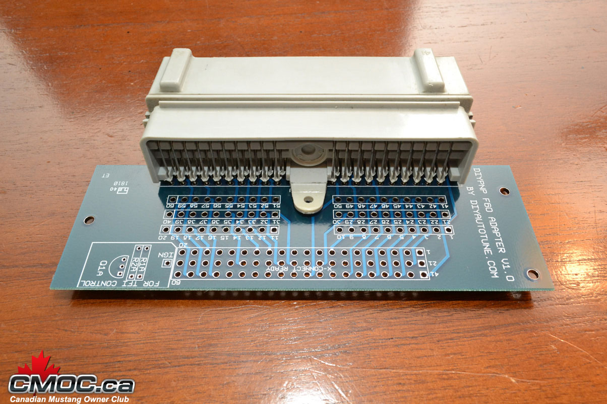
It looks like the pinout on the DIY website lists ECU pins (3k, 4F, 1U, etc) where the connector board is numeric (1-60 pictured above). Has anyone documented the "conversion" between the 2 or is the best option to simply trace the ecu pin to the numeric pin on the connector board, then to the pin on the main board?
It appears there are 2 sets of holes for each connection on the connector board. Is there any significance to which hole is used or are you simply using the most convenient one?
Sorry for the stupid questions, just trying to make sure I understand what's going on.
I just have a couple questions on the connector board:
It looks like the pinout on the DIY website lists ECU pins (3k, 4F, 1U, etc) where the connector board is numeric (1-60 pictured above). Has anyone documented the "conversion" between the 2 or is the best option to simply trace the ecu pin to the numeric pin on the connector board, then to the pin on the main board?
It appears there are 2 sets of holes for each connection on the connector board. Is there any significance to which hole is used or are you simply using the most convenient one?
Sorry for the stupid questions, just trying to make sure I understand what's going on.
MFz Lurker
Joined: Aug 2011
Posts: 9
From: Fort Myers, FL
I found a thread on MT.net that answered my first question. Apparently the Mustang board pictured was just different from the Miata boards and labeling on the board matches the stock harness pins. Makes a lot more sense now.
Miata connector board:
Miata connector board:

!!!! I NEED TO POST !!!!
Joined: Oct 2013
Posts: 4
From: N. Carolina
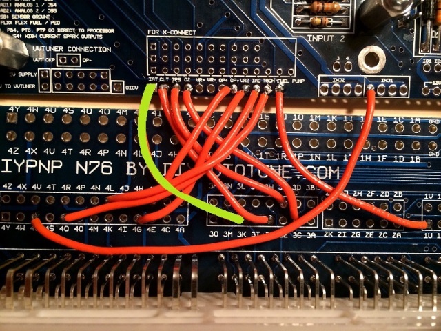
it's really not hard. Say you have a '91.
Instead of wiring 1Q (the a/c switch) to Input 1 IN then back OUT to 1J, simply completeing a circuit.
You'd wiring 1Q to Input 1 IN, The input 1 OUT to PE1.
Then from PAO to 1J.
Now, when the A/C switch is grounded, the MS knows, it can bump up the idle, then ground the output to 1J.
Instead of wiring 1Q (the a/c switch) to Input 1 IN then back OUT to 1J, simply completeing a circuit.
You'd wiring 1Q to Input 1 IN, The input 1 OUT to PE1.
Then from PAO to 1J.
Now, when the A/C switch is grounded, the MS knows, it can bump up the idle, then ground the output to 1J.
Just wanted to make sure this is still the recommend way to wire the A/C on a v1.5 DIYPNP for a 1990.
!!!! I NEED TO POST !!!!
Joined: Oct 2013
Posts: 4
From: N. Carolina

